The LCD module can be connected to an Arduino board in two ways:
- Direct connection from the LCD module to the Arduino board (No I2C/IIC)
- LCD Module and Arduino board connected through an I2C Module
DIRECT CONNECTION
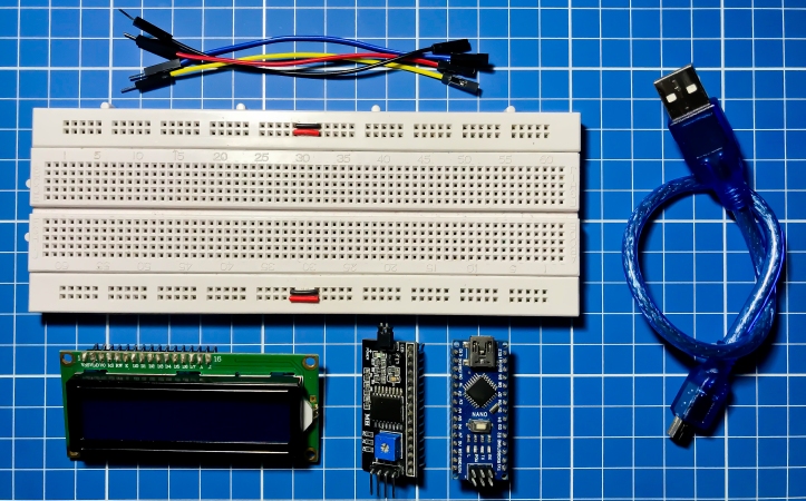
Components needed for direct connection:
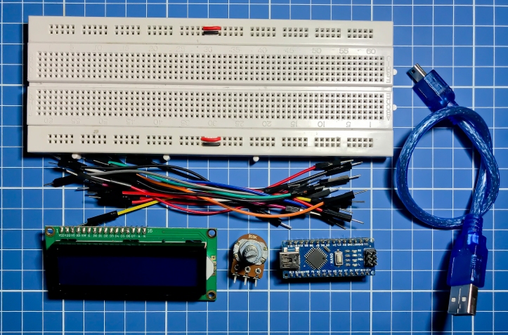
- Arduino Nano + USB connector (Although most Arduino boards can be used as well)
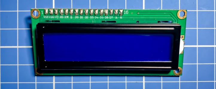
- LCD Module (we will be using the 1602 module – 16 characters per row, 2 rows)
- Rotary potentiometer (we will be using a 10K-ohm potentiometer)
- Lots of jumper wires (I am using 16 jumper wires)
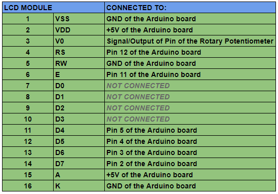
For us to be able to connect the module to an Arduino board, we need to study first the pins of the LCD module. The image below shows the pinout of for the LCD Module (1602):
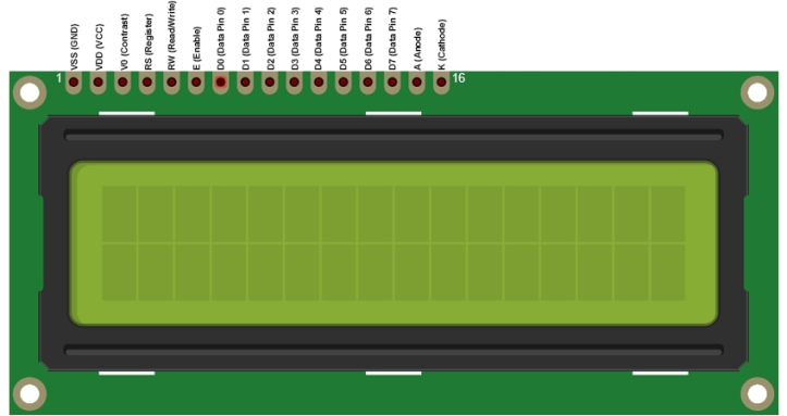
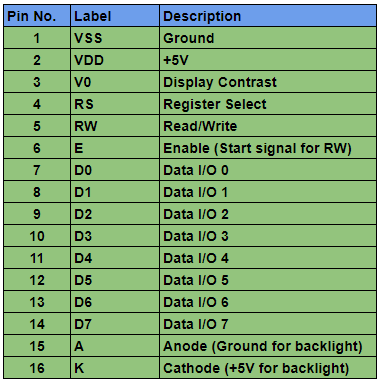
Usually, the module’s pins are labeled 1 (leftmost pin) and 16 (rightmost pin). This gives us the order of the pins from 1 – 16. To better clarify the pin labeling, please see below:
We take a look at the schematics for this experiment:
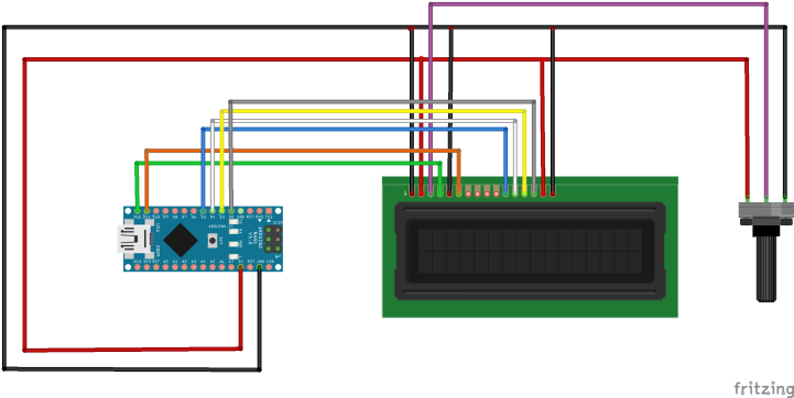
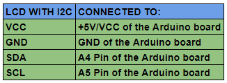
Table below explains the connections among these components:
The potentiometer has to be powered as well, so connect its VCC and GND pins to the +5V and GND pins respectively of the Arduino board of your choice (refer to the schematics for the VCC and GND pins).
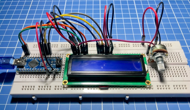
Set the needed components up to the breadboard, and the setup should similarly look like the image shown below:
Connect the Arduino board to the PC via a USB connector (usually supplied with your board when you buy one). We are now ready to upload some example sketches to our Arduino board. Luckily, the Arduino IDE has a built-in ready example for our set up. The first part of the sketch explains the pin connections from the LCD module to the Arduino board, and this matches our schematics.
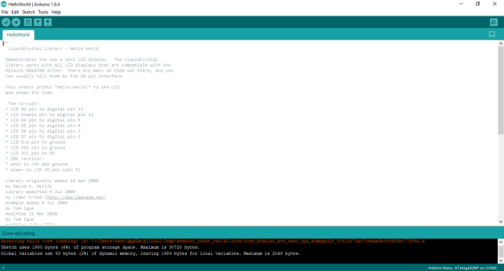
Open an example sketch for the LCD. In this experiment, we will use the HelloWorld sketch:
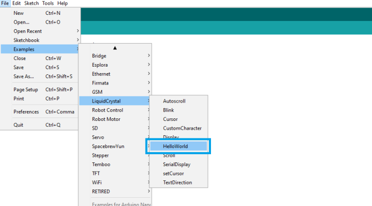
You should see something like this:
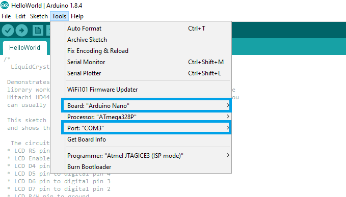
As said previously, the first part of the sketch explains the pin connection of the LCD module to the Arduino board. The next thing to do is to upload this sketch to the Arduino board. However, before that, we need to check if were have selected the right board, the and the right COM where the Arduino is connected to (for other boards, please select the right configurations as required by the board):
We are now ready to upload this example sketch. To upload this sketch, the shortcut CTRL + U can be used. Uploading sketches can also be done by going to Sketch > Upload in the menu, or click the arrow (pointing rightward), just below the menus:

After uploading the sketch, you should be seeing something like this in your LCD:
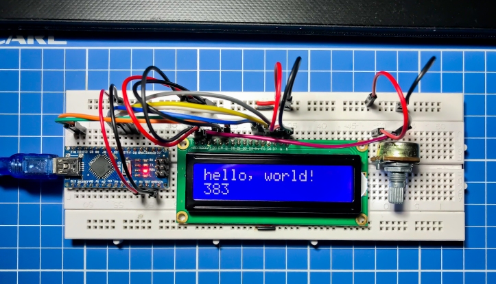
IMPORTANT: If you are not seeing anything (or maybe only white blocks) in the LCD screen, then you might want trying to adjust the contrast of the display via the potentiometer. Turn it left or right until the output can be seen in the display.
VIA THE I2C (IIC) MODULE
Components needed for direct connection:
- Arduino Nano + USB connector (Although most Arduino boards can be used as well)
- LCD Module (we will be using the 1602 module – 16 characters per row, 2 rows)
- I2C (IIC) module (If your have the I2C module already soldered to the LCD module, the better)
- Few of jumper wires (I am ONLY using 4 jumper wires!)
The schematics shows the connection between the LCD Module and the I2C module. We connect the I2C module to the Arduino board, using only 4 wires. Let’s look at the schematic below.:
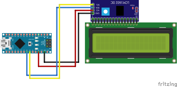
Connect the VCC pin of the I2C module to 5V pin (VCC) of the Arduino board. The GND pin of the I2C module should be connected to the GND pin of the Arduino board. SDA and SCL pins of the I2C modules should be connected to A4 and A5 pins of the Arduino board respectively:
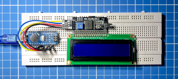
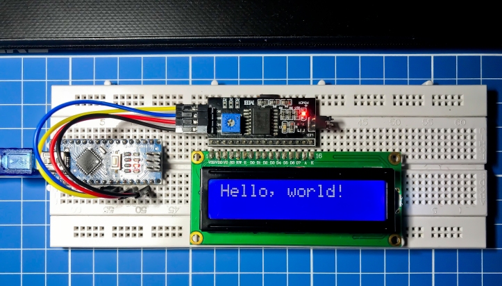
Some LCD modules already have the I2C module attached to them (soldered). This is actually better, as we don’t need a breadboard to connect the modules together. In our experiment, we will assume that the I2C module isn’t soldered to the LCD module. If the schematics above is followed correctly, the setup should be similar to what is shown below:
Now, the setup is complete. However, we still need to add the library for the I2C version of the LCD module. You can download the library from Liquid Crystal I2C Library (And Samples too!).
Since we are using an I2C module, we need to determine the address of the device. You can then Upload first the I2C Scanner to your Arduino board, open the Serial monitor (be sure you are in the correct COM port). The I2C Scanner sketch can be found in the Arduino web site: I2C Scanner.
For a detailed instruction on how to add these libraries, please visit one of my articles entitled Displaying Text to LCD via i2c Module on DIY Arduino Board.
NOTE: You need to upload first the I2C Scanner sketch to the board to determine the address of your I2C module. After you’ve determine its address, then the sample sketches for the Liquid Crystal I2C can then be uploaded, since the sample sketches requires the I2C address.
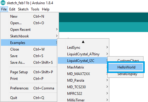
Now, open the HelloWorld sketch under LiquidCrystal_I2C examples:
Sketch is something similar as below. The text inside the blue rectangle in the sketch is the address of the I2C device, but yours might have a different one – the reason why we need to upload the I2C Scanner sketch and determine the address by opening the Serial Monitor in the Arduino IDE:
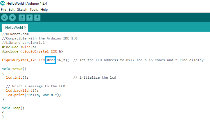
Now, upload this sketch (be sure to change the address, since this might be different as yours. Mine is 0x3F). The output should be the same as shown below:
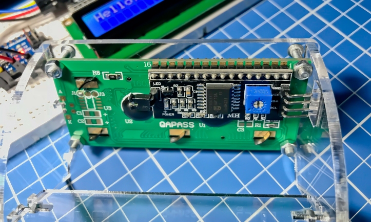
By the way, this is how it looks like when the I2C module is already soldered to the LCD Module:
Comments are welcome, especially correction to this article. I will have them corrected once I have verified that these indeed need correction.
I hope this simple tutorial helps.
Thank you very much.

Thank you for this tutorial. There is a mistake at the top of the second table. LCD’s VSS pin sholud be connected to GND not +5V.
LikeLike
Thank you very much for that! I will have this corrected now. Thanks for the correction, I really appreciate it much. I will send another reply once the correction has been made.
THANKS!
LikeLike
Hi pkrzysk, the correction is already made. Thanks for finding that out!
LikeLike
Thank you so much! Works PERFECTLY! AWESOME!
LikeLike