

How about connecting your Arduino board to the Internet? That is made possible by using ESP8266 ESP-01 Wifi Module. I will also write a separate article on using the ESP8266 ESP-01 Wifi Module as a standalone board in an IOT project. IOT by the way means “Internet of Things” – this is an inter-networking of physical devices connected to the Internet, which can collect and exchange data (more on Wikipedia at Internet of Things). We will use Cayenne as our IoT platform. Please register for a FREE account at https://cayenne.mydevices.com.
PINOUT
We would like to know the pinout of the module first. Refer to the image below for labels:

VCC takes 3.3V. So you have to be careful with the power going to the board. RX also receives 3.3V logic, so better create a voltage divider to cut the voltage down to 3.3V. GPIO0 and GPIO2 will be discussed further in a separate article. GPIO0 for instance is connected to ground during programming mode. TX can be connected directly to a pin without the need for the voltage divider. CH_PD is connected to 3.3V.
I created a simple diagram using EasyCircuit app to demonstrate voltage divider:

ACTUAL IMAGE
Below is an actual image of ESP8266 ESP-01.

CONNECTION TO ARDUINO UNO
The first thing that I did was to test the wifi module. I connected the module to the Arduino UNO as seen in the schematic below (by the way, the schematic below was created online at Tinkercad. Prior doing this setup, please upload a Bare Minimum sketch on your Arduino board! Also, be sure that the ESP8266 ESP-01 module hasn’t been uploaded yet with any sketches, only the firmware that went with it. I will also write an article on how to flash a firmware to the board.

CONNECTIONS FOR AT COMMANDS
I made a table of connections between the Arduino UNO and the ESP8266 ESP-01 Wifi Module:
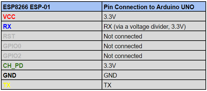
YES! You connect RX of the wifi module to the RX of the Arduino UNO board, and the TX of the wifi module to the TX of the Arduino board.
The colors above (for those with connection to Arduino UNO) will correspond to the jumper wire color connecting the respective pins. This is to minimize confusion during the actual wiring.
Now that we’re done with the wiring, let’s move on to executing AT Commands to ESP8266 Wifi Module via the Arduino UNO board. We may now plug the USB of the Arduino UNO board to your computer.
Open Arduino IDE.
Go to Tools > Port. (Be sure Arduino UNO is selected under Board.)
Now, open the Serial Monitor by pressing Control + Shift + M or by just clicking the lens icon at the top right portion of the IDE just below the menu bar.
By default, some modules are set to 115200 baud rate. Set the baud rate if it isn’t 115200. Both NL & CR should be selected as well. You may refer to the bottom portion of the IDE, bottom right portion. Screenshot below:

We are now ready to execute AT Commands. Do the following:
- Type AT then press ENTER. The response from the wifi module should be OK.
- Type AT+GMR then press ENTER. The response from the wifi module should be the firmware version of the module, then an OK from the module.
- Type AT+CWMODE=1 then press ENTER to set it to Station Mode (client).
- Type AT+CWLAP then press ENTER. The response should be a list of wifi access points in your area, then an OK response from the module.
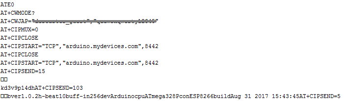
If no errors were returned when executing these commands, we are now ready for the actual coding of our sketch. Below is the screenshot of my serial monitor when executing the AT Commands:

ENTER INTERNET OF THINGS!
We are now ready to connect our device to the Internet! Be sure you already registered for a FREE Account at https://cayenne.mydevices.com, since we will be using this platform to control our device remotely over the Internet.
We need to modify the RX and TX connections to our Arduino UNO board. Also, we will be adding three (3) LEDs which we will be controlling via the Internet. Here is the updated schematics:

The schematics above is a modified version of the first one. AND YES, this time, Arduino TX goes to ESP8266 RX via voltage divider (3.3V) and Arduino RX goes to ESP8266 TX. The first one was to test the execution of AT Commands. The modified version let’s you connect to the Internet via the Cayenne IoT platform, plus I have added some more components:
- Three (3) LEDs (red, blue and green)
- Three (3) 220-ohm resistors (for the LEDs)
Refer to the modified connections of the Arduino UNO board to the ESP8266 ESP-01 Wifi Module:

SETTING UP DEVICE IN CAYENNE
Log on to your account at Cayenne’s Login Page. Be sure to register for an account, if you haven’t still at Cayenne’s Signup Page.
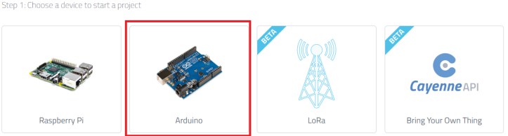
STEP 1. Choose your device. After successfully logging in, you will be asked to select the device you want to connect to the platform. I selected Arduino:
STEP 2. You will be asked to set up Arduino in your local machine. There are instructions on how the libraries are added in the Arduino IDE and where to find them:

STEP 3. You will be asked to connect your Arduino. However, what we need here is just the AUTH TOKEN FOR THIS DEVICE value. Look at the top right portion of the screenshot. You may have a different value for this.

Before we begin with our sketch, we need to set up the needed libraries. This is excluded from the standard library we have for Cayenne. You may find the needed libraries and instructions in this Cayenne Forum thread. You will need to have this set up before proceeding. The needed files need to be set up:
The said files need to be renamed. The first one, after downloading it should be renamed from CayenneESP8266Shield.log to CayenneESP8266Shield.h. The second one should be renamed from ESP8266HardwareSerial.log to ESP8266HardwareSerial.zip. Place CayenneESP8266Shield.h inside the C:\Users\<username>\Documents\Arduino\libraries\Cayenne folder. Add ESP8266HardwareSerial.zip to the Arduino library via the Arduino IDE.
If every thing is set up correctly, then we’re ready to go. Have a at the code below:
/*
 Cayenne ESP8266 Shield WiFi Example
 Adapted from Blynk's ESP8266_Shield_HardSer Example

This sketch connects to the Cayenne server using an ESP8266 WiFi module as a shield connected
 via a hardware serial to an Arduino.

You should install the ESP8266HardwareSerial.zip library via the Arduino IDE (Sketch->Include Library->Add .ZIP Library)
 from the Cayenne extras/libraries folder (e.g. My Documents\Arduino\libraries\Cayenne\extras\libraries) to compile this example.

NOTE: Ensure a stable serial connection to ESP8266!
 Firmware version 1.0.0 (AT v0.22) or later is needed.
 You can change ESP baud rate. Connect to AT console and call:
 AT+UART_DEF=115200,8,1,0,0

For Cayenne Dashboard widgets using digital or analog pins this sketch will automatically
 send data on those pins to the Cayenne server. If the widgets use Virtual Channels, data
 should be sent to those channels using virtualWrites. Examples for sending and receiving
 Virtual Channel data are under the Basics folder.
*/

//#define CAYENNE_DEBUG // Uncomment to show debug messages
//#define CAYENNE_PRINT Serial1 // Comment this out to disable prints and save space
#include <CayenneESP8266Shield.h>

// Cayenne authentication token. This should be obtained from the Cayenne Dashboard.
char token[] = "i2mct9ol2w"; // This is the Auth Token

// Your network name and password.
char ssid[] = "wifi name";
char password[] = "wifi password";

// Set ESP8266 Serial object
#define EspSerial Serial

ESP8266 wifi(EspSerial);

void setup()
{
 //Serial1.begin(9600);
 delay(10);
 // Set ESP8266 baud rate

EspSerial.begin(115200);
 delay(10);

Cayenne.begin(token, wifi, ssid, password);
}

void loop()
{
 Cayenne.run();
}
Before uploading this sketch to your Arduino Uno board, remove the TX and RX connections first. Arduino Uno’s TX and RX pins should not have any wires connected to them. Select Ardiuino/Genuino Uno under Boards:

Upload this sketch. After having successfully uploaded the sketch, unplug the Arduino Board then put the RX and TX connections back (Arduino RX to ESP8266 TX, and Arduino TX to ESP8266 RX via voltage divider).
Plug the Arduino Uno board once again to the computer. The Arduino board should now be starting to connect to wifi, and eventually connect to Cayenne. You may open the Serial Monitor to see what’s going on. Default baud rate should most likely be 115200. If you see something similar to the screenshot of the Serial Monitor below, your Arduino Uno connected to Cayenne platform successfully:
Go back to the Cayenne page where you left off. The page changes once the board has successfully communicated with Cayenne platform. Here is how it will look like afterwards:

We are now ready to put some widgets to the board. Our goal now here is to create 3 buttons to trigger the turning on and off the LEDs. Refer to the schematics for the LED connections to Arduino Uno.
Now, referring to the current page at Cayenne, you will see a green object with “Add new…” label. Click on that one. Then choose “Device/Widget”:

Scroll down and click on “Light” under “Actuators”:

Then select “Light Switch”:

We configure the widget as follows, as shown in the screenshot below:

Widget Name : Red LED
Select Device : Arduino
Connectivity: Digital
Pin: D13
Choose Widget: Button
Choose Icon: LED
You may may ignore “Step 1: Sketch file”. Click “Step 2: Add Actuator”. Be sure the Arduino Uno is still connected online. You will not be able to add the widget if the board is offline. After adding the widget, here is what it looks like:

Now, do the same thing to the rest of the LEDs (for blue and green LEDs). In the schematics, blue is connected to Digital Pin 12 (D12) and Digital Pin 11 (D11) respectively. The final appearance of the dashboard should now look like:

Press the widgets randomly. This should turn on or off the LEDs on your Arduino Uno board.
You may also download Cayenne iOS or Android app. Log on using your credentials, and you will be able to control the LEDs via your smartphone. Screenshot below is the iOS app GUI for Cayenne:

Kinda fun, right?
This tutorial actually serves as a documentation for myself. I hope this helps you as well.
Should you need to correct something or make some comments or even suggest a method, please do email me at eldontronics@gmail.com.
Thank you very much.

[…] to set your Arduino board Arduino IDE, and the libraries. We already covered this in our previous tutorial. Click the Next button […]
LikeLike
[…] learned from the previous posts (Beginning IoT with Cayenne Platform and ESP8266 ESP-01, and IoT with Cayenne Platform and USB Serial Connection) about how a component is controlled over […]
LikeLike
Nice tutorial but I had to change the EspSerial baud rate to 9600 to get this working.
LikeLiked by 1 person
The links for CayenneESP8266Shield.log and ESP8266HardwareSerial.log are broken. These files can be found at http://community.mydevices.com/t/wifishield-with-arduino-uno-compiling-error/1269/11
LikeLiked by 1 person
Hi adam, thanks for this!
LikeLike
Hi adam! Just updated the links. Links aren’t broken anymore. 🙂
LikeLike
Love this thanks for writing it up!
LikeLiked by 1 person
One of the nicer tutorials I’ve seen. Unfortunately, after compiling the code and reconnecting the rx/tx pins as well as the usb, my serial monitor continues to cycle through trying to connect to Arduino.mydevices.com over and over again.
LikeLike
Hi Cliff, I will try to replicate your issue… had this tested several times before publishing. But I’ll investigate as why you are experiencing this. thanks!
LikeLike
ATE0
AT+CIPCLOSE
AT+CIPSTART=“TCP”,“arduino.mydevices.com”,8442
AT+CIPCLOSE
AT+CIPSTART=“TCP”,“arduino.mydevices.com”,8442
AT+CIPCLOSE
AT+CIPSTART=“TCP”,“arduino.mydevices.com”,8442
AT+CIPCLOSE
AT+CIPSTART=“TCP”,“arduino.mydevices.com”,8442
AT+CIPCLOSE
AT+CIPSTART=“TCP”,“arduino.mydevices.com”,8442
AT+CIPCLOSE
AT+CIPSTART=“TCP”,“arduino.mydevices.com”,8442
That is the feedback within the serial monitor. I have read some forums that suggest I need to flash the firmware on the chip, but I had no luck doing that with python/pip and nodemcu.
LikeLiked by 1 person
what is wrong if I directly connect RX pin to 3.3V Arduino pin?
and neglect using a voltage divider?
will my esp by safe?
LikeLike
What’s wrong? Your module will not be able to receive signals from your Arduino. That’s what’s wrong. Please study the tutorial heartily, as I tested it, while writing the tutorial. Study the purposes of RX and TX.
LikeLike
Any one had this problem ‘Error” in Arduino?
it only happen when you connect TX and RX pin to something!
avrdude: stk500v2_ReceiveMessage(): timeout
avrdude: stk500v2_ReceiveMessage(): timeout
avrdude: stk500v2_ReceiveMessage(): timeout
avrdude: stk500v2_ReceiveMessage(): timeout
avrdude: stk500v2_ReceiveMessage(): timeout
avrdude: stk500v2_ReceiveMessage(): timeout
avrdude: stk500v2_getsync(): timeout communicating with programmer
An error occurred while uploading the sketch
LikeLike
When correctly co figured, connecting RX and TX to something should not show these errors. Have you followed the tutorial correctly?
LikeLike
finally, the damn esp8266 make my RX0 and TX0 of pin 0 and 1 of my Arduino got damage!
LikeLike
I don’t think you followed the steps correctly. Even if you connect RX0 and TX0 of Arduino to Rx and Tx of esp8266, your board should not get damaged. If you damage those pins, you might have supplied more than 5v to your Arduino pins. Or, erroneously followed the tutorial. Many have followed my tutorial, and none got this problem.
LikeLike
Did you use resistors when between TXD of Arduino and RXD of ESP8266?
LikeLike
Mr Eldon I totally followed your guide !
at first that connection worked for me and my esp responsed to AT command then yesterday I tried the same connection but i got above error!
Remember I’m still at first step to make my esp8266-01 to respond AT command mode!
And I didn’t upload any code just upload the blank page to let esp work!
LikeLike
What about tje other tutorial you were following as you said in the email? You said you also tried other tutorials.
LikeLike
Hi sir Eldon,
I hae followed your tutorial on the dot, even tried it with 3 esp modules, 2 of them the esp-01s and one thestandard esp8266.
None of them work, but both esp-01s shortly turn on the blue led and then turn to the OFF state.
The standard esp8266 red led goes on and stays on.
But none of them give any reaction on the AT command.
I have not tried any tuts before with the second one of the esp-01s and the standard esp8266.
Do you have any idea what could I have missed ?
LikeLike
Can you send me the actual photo of your work sir? I already have suspiscions, but I need to see how you did your setup. Uou can send ot via email at eldonteonics@gmail.com.
LikeLike
dear Eldon
Since the Cayenne MQTT is updated!!! The below two files are not useful anymore .could you please send me the latest one .thanks alot
CayenneESP8266Shield.log
ESP8266HardwareSerial.log
LikeLiked by 1 person